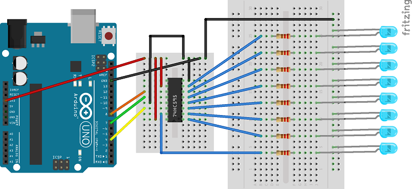
I had this little project in mind but after chewing on it for a while I figured that to achieve my goal I would need more pins than the Arduino Uno can offer. I started looking at what my options were and soon I found something that looked very promising – shift registers (yes, I realize that this is a very basic stuff for people familiar with elementary electronics but sadly I am not one of them). Conceptually, the way shift registers work is simple – you feed a shift register bit by bit (serial-in) and then tell it to output all data at once (parallel-out). (The opposite (i.e. parallel in, serial out) is also possible but this is out of scope of this post.) Translating this to Arduino terms – with one output pin to send the data and a couple of additional output pins to control the shift register we can have tens of output pins. In the simplest case “tens” means actually 8 but shift registers can be cascaded and each additional register adds 8 additional output pins. To try this out I got myself a few 74HC595 shift registers and a bunch of LEDs and resitors and build this circuit:
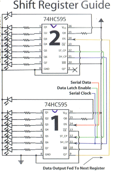
One thing that turned out to be very helpful was a small sheet I got when I bought the shift registers showing how to cascade them. Even though I was not cascading shift registers (I was too cheap and bought just 10 LEDs) it helped me connect all the power and ground wires to the correct pins. I actually decided to scan the sheet and attach it to this post because I am sure I will lose it sooner than later and won’t be able to find it when I need it. Here it is:
Then I had to breathe some life into all the wires and ICs so I wrote some code. I was surprised when it turned out that you literally need less than 10 lines of code (and some data) to get the whole thing up and running:
And here is the code:
int clock = 8;
int data = 4;
int latch = 7;

uint8_t patterns[] =
{
  0x00, 0x01, 0x02, 0x04, 0x08, 0x10, 0x20, 0x40, 0x80,
  0x00, 0x01, 0x02, 0x04, 0x08, 0x10, 0x20, 0x40, 0x80,
  0x00, 0x00,
  0x01, 0x03, 0x07, 0x0f, 0x1f, 0x3f, 0x7f, 0xff, 0x00,
  0x01, 0x03, 0x07, 0x0f, 0x1f, 0x3f, 0x7f, 0xff, 0x00,
  0x00, 0xff, 0x00, 0xff,
  0x00, 0x00,
  0x81, 0x42, 0x24, 0x18, 0x24, 0x42, 0x81,
  0x81, 0x42, 0x24, 0x18, 0x24, 0x42, 0x81,
  0x00, 0x00,
};

void setup() {
  pinMode(clock, OUTPUT);
  pinMode(data, OUTPUT);
  pinMode(latch, OUTPUT);
}

void loop() {
  static int index = 0;

  digitalWrite(latch, LOW);
  shiftOut(data, clock, MSBFIRST, patterns[index]);
  digitalWrite(latch, HIGH);
  delay(300);

  index = (index + 1) % sizeof(patterns);
}
The code is simple. Since I have just 8 LEDs I can use a byte value to control which of the LEDs should be on. If a bit corresponding to an LED is set to 1 I will turn the LED on, otherwise I will turn it off. The values are stored in an array and every 300th millisecond or so I take the next value from the array and use it turn the LEDs on or off. When I reach the end of the array I start from the first element. Even though the code is so simple there are two interesting bits there. The first one is controlling the shift register. The second one (related to the first one) is how the shiftOut function works. As I said above we need three wires to control the register. They are connected to pins labeled as latch, clock and data in the code. We set latch to LOW to tell the shift register that we are going to send data. Once we send all the data we need to set latch to HIGH. To send the data we use the shiftOut function. What this function does is it reads the passed value bit by bit and for each bit it sets the clock pin to LOW then it sets the data pin to LOW or HIGH depending on the value of the bit and then it sets the data pin to HIGH. It is actually pretty easy to write a counterpart of the shiftOut function on your own. Here is what I came up with (I skipped the bitOrder parameter as I did not need it):
void myShiftOut(uint8_t dataPin, uint8_t clockPin, uint8_t val)
{
  for(int mask = 0x80; mask > 0; mask >>= 1)
  {
    digitalWrite(clockPin, LOW);
    digitalWrite(dataPin, val & mask);
    digitalWrite(clockPin, HIGH);
    digitalWrite(dataPin, 0);
  }
  digitalWrite(clockPin, LOW);
}
You can replace the call to the shiftOut function with a call to the myShiftOut function in the first snippet and it will continue to work the same way.
That’s more or less it. Simple but very powerful (and fun)!

Hi, thank you so much for posting this tutorial! I’m using it to run an array of haptic feedback motors. Unfortunately I don’t know what it is you used to write the patterns (0x00), could you point me in the right direction?
LikeLike
What do you mean by “write the patterns (0x00)”? shiftOut writes the data serially which is what the shift register expects. The project uses 8 LEDs therefore 1 byte is exactly what is needed to control given LED – if a bit is set the corresponding LED will be lit. shiftOut takes this byte and serializes it (although code that shows how to do it manually is also included).
LikeLike