Some days are worse than other. On these bad days you don’t feel like working, people are constantly interrupting and, in general, not much is being done. When I have a day like this I use the Pomodoro technique to get back on track. The basic idea of the Pomdoro technique is that you try to focus solely on your work for 25 minutes minimizing all external and internal interruptions. You measure the time using a tomato shaped kitchen timer and hence the name – Pomodoro. Using the actual Pomodoro timer might seem like a good idea at first but in reality is not. The timer is ticking quite loudly which is annoying not only for you but also for people around. Using a software timer (I tried http://timemanage.me/) did not work for me either – other people can’t see it so it is impossible for them to know you are in the middle of your Pomodoro. On top of that you can’t check how much time is left without switching windows and losing focus which contradicts the very goal of Pomodoro (i.e. avoiding interruptions). This is why I decided to build my own Pomodorro timer. The requirements were simple – the timer had to be standalone so that I could check how much time is left with just one glimpse. To help prevent from external interruptions it also needed an indicator showing other people that I am busy. Meeting the first requirement was quite simple – a TM1637 based 4-digit LED display seemed good enough for the job. The second one was a bit harder. I got a little creative and bought a mood enhancing light (you should have seen my wife’s face when I showed her what I ordered) on Amazon. Now, that I got two most important parts the rest of the project was quite easy. I needed a few more parts like Arduino board (I went with Arduino Nano because of its size), a button (needed for restarting the timer), a color LED (to light my cube to indicate when I am busy) a small breadboard and a handful of resistors and jumper cables. This is the end result:
This project is quite easy but is really fun. You can try building a timer like this yourself. First connect the parts as shown on this picture:
Once the hardware part is done you need to upload the code to control the circuit. You can find the sketch in my ArduinoPomodoroTimer github repo. The most complicated part of the code is setting up the interrupt handler. I took it from my other project where I built a digital clock using an LCD display from an old Nokia phone. Take a look at this post for more details. Another complex piece is handling the LED display. Again, I wrote a very detailed post on this very subject a while ago so take a look at it to understand the code. The rest of the code is just about changing the color of the LED when the timer reaches 0 and reacting to button presses and is pretty straightforward.
In one of my Arduino projects I needed to show some numbers. Luckily, a 4 digit display lain around on my desk. Because it had a built-in driver which would save me from all the hassle with shift registers it looked like a perfect fit. I checked the chip the display was using and it was labeled “TM1637”. I was already familiar with the TM1638 (for more details see my recent post about using a TM1638 based board with Arduino) chip so I thought making the TM1637 work should be easy. Unfortunately, while there are some similarities between the chips getting the TM1637 to work took me longer than I had expected. When I finally aligned all the moving pieces I decided to create a standalone sample which will hopefully be helpful to other people playing with TM1637 based displays. To make the sample a good demo I just took my Nokia LCD clock sample, replaced the Nokia LCD display with the TM1637 display and updated the code accordingly and ended up with a TM1637 clock: TM1637 clock
Let’s get started from taking a closer look at the TM1637 display. The TM1637 display has four pins VCC, GND, DIO, CLK. Similarly to the TM1638 the TM1637 uses a protocol to communicate with the display. While commands themselves are very similar to the ones used by the TM1638 board sending the data is a little different. The display does not have the STB pin the TM1638 board had so separating commands and arguments works differently. A start signal needs to be sent before sending a command to the display. Once the command has been sent a stop signal needs to be used. If a command has arguments another start signal needs to be sent and then after all arguments have been sent the stop signal needs to be used. The start signal is just setting the CLK and DIO pins to HIGH and then setting them to LOW. The stop signal is setting the CLK and DIO pins to LOW and then to HIGH. The CLK pin should not change the state more frequently than 250kHz so I added a little delay between state changes. Here is how my corresponding start and stop functions look like:
The first command just initializes the display and sets the brightness. This is done by sending the %1000abbb value where the a bit activates (if set to 1) or deactivates (if set to 0) the display and the bbb bits control the brightness (with 000 being the darkest and 111 being the brightest).
The second command allows controlling a single digit of the display. It requires sending 3 bytes to the display: 0x44 %110000aa X where the aa bits in the second byte are used to select the position of the digit to control while X is the value to be displayed encoded in the standard 7 segment coding (as explained here).
Finally, the last command is used to control multiple digits and can consists of up to 6 bytes. Typically you want use all the digits in which case you send the following bytes to the display – 0x40 0xC0 W X Y Z. The first byte is the command identifier the second byte tells the display to start at the first position and W X Y Z are the values to be displayed on subsequent positions (again in the standard 7 segment encoding).
Here are is a short summary of commands:
START (0x88|%00000aaa) STOP
initialize and set the brightness
START 0x44 STOP START (0xC0|%000000aa) X STOP
display value X at position %000000aa
START 0x40 STOP START 0xC0 W X Y Z STOP
display values W X Y Z starting from position 0
When sending data to the display timing is the tricky part. Apparently (if I understood the machine translation of the data sheet which is in Chinese correctly), the CLK pin should not change the state more frequently than 250kHz. This means that I could not use the Arduino shiftOut function because it does not allow to provide the delay after setting the DIO pin. Instead I had to come up with my own function (I called it writeValue) that emulates the shiftOut function but which uses a delay after setting the DIO pin. (Yes, it did made me think that my other projects may have some kind of issue due to writing data too fast but, hey, they worked!). Another thing is that the chip is acknowledging it received data successfully by setting the DIO pin to HIGH after each byte of data has been written. I have never seen it fail and am not even sure what I would be supposed to do if it did. Probably in my little projects this does not matter too much – I am constantly writing to the display so I hope that a subsequent write will succeed and therefore even though the writeValue function returns a result I am ignoring it. The writeValue function looks as follows:
At long last I set out to work on one of my Arduino projects when I realized that I didn’t have any 4-digit 7 segment LED display at home. Since it was quite important part of the project I went to ebay and started looking for something when I found this:
This is an “8-Bit LED 8-Bit Digital Tube 8-Bit Key TM1638”. It seemed to be a very good fit for my project since it not only had the display but it also had some buttons – something I needed too. In addition it had only three control lines which would simplify things a lot by sparing me from dealing with shift registers on my own – something I would have to do had I used the cheapest 7 segment LED display. When I got the board I got baffled a little bit. It was just a piece of hardware without any documentation. I deciphered the symbol on the chip and went for a quest to find some information about how it worked. I found a data sheet but it was mostly in Chinese. Unfortunately 我的中文不好, so I only skimmed it and continued looking. I quickly found that there is a library I could use. However I did want to learn how the thing I bought actually worked, so I spent some time more time looking for more information about the board. Finally, I found this page which turned out to be the most helpful and allowed me to start experimenting.
As I already mentioned the board has just 3 control pins plus power and ground. The control pins are strobe, clock and data. The strobe and clock pins are only OUTPUT while the data pin can be both OUTPUT and INPUT. The strobe pin is used when sending data to the board – you set the strobe pin to LOW before you start sending data – one or more bytes – and then set the strobe pin back to HIGH. Note that there is just one data pin which means the data is being sent 1 bit at a time. This is where the clock pin comes into play. When sending data you set the clock pin to LOW then you set the data pin and set the clock pin back to HIGH to commit the bit value. You are probably already familiar with this pattern (if not take a look at this post) – it is the standard way of sending data with shift registers and therefore we can just use the standard shiftOut function to send 8 bits of data with just one line of code.
The data sent to the board follow a protocol where the first byte tells the board what we want to do (I call it ‘command’) and is followed by zero or more bytes that are arguments for the selected function. Arguments are sent separately (i.e. the strobe pin needs to be set to HIGH after sending the command and again to LOW before sending arguments). The board has 4 functions:
activate/deactivate board and initialize display
write a byte at specific address
write bytes starting from specific address
read buttons
To activate the board and set the display brightness we use the 1000abbb (0x8?) command where the bit marked as a is used to activate/deactivate the board and bits marked as bbb are used to set the brightness of the display. For example to activate the board and set the brightness of the display to the maximum value we need to send 0x8f. This function does not have any arguments.
To write a byte at specific address we send the 010000100 (0x44) command followed by the address in the form of 1100aaaa (aaaa bits denote the location we want to write to) followed by the value. For example to write the value 0x45 at address 0x0a we would have to send the following sequence of bytes: 0x44 0xca 0x45.
If we want to write values at consecutive addresses (very helpful to reset the board) we would send 01000000 (0x40) followed by the starting address (again in the form of 1100aaaa) followed by the values we want to write. For instance if we send 0x40 0xc0 0x00 0x01 0x02 0 would be written at address 0, 1 would be written at address 1 and 2 would be written at address 2. Note that we have 4 bits to select the address which means there are sixteen locations that can be written to. If you continue writing after reaching the address 0x0f it will wrap and you will start again from address 0x00.
To read buttons we send the 010000010 (0x42) command, set the data pin as INPUT and read 4 bytes containing button status.
Command
Arguments
Description
0x8? (1000abbb)
(none)
activate board (bit a), set brightness (bits b)
0x44 (01000100)
0xc? 0x??
write value 0x?? at location 0xc? (single address mode)
0x40 (01000000)
0xc? 0x?? 0x?? 0x??
write values 0x?? starting from location 0xc? (address auto increment mode)
0x42 (01000010)
N/A
read buttons
Now we know we can write values to one of the 16 locations. This is the way we turn LEDs on and control the display. The board has two 4 digit 7 segment LEDs displays and 8 LEDs. Each of them has a dedicated address to which a value needs to be written to control the corresponding item. For instance if to turn on the first LED we would write 1 at address 0x01. Below is a list of locations with short explanations.
Address
Description
0x00 (0000)
display #1
0x01 (0001)
LED #1 00000001 – red, 00000010 – green
0x02 (0010)
display #2
0x03 (0011)
LED #2 00000001 – red, 00000010 – green
0x04 (0100)
display #3
0x05 (0101)
LED #3 00000001 – red, 00000010 – green
0x06 (0110)
display #4
0x07 (0111)
LED #4 00000001 – red, 00000010 – green
0x08 (1000)
display #5
0x09 (2001)
LED #5 00000001 – red, 00000010 – green
0x0a (1010)
display #6
0x0b (1011)
LED #6 00000001 – red, 00000010 – green
0x0c (1100)
display #7
0x0d (1101)
LED #7 00000001 – red, 00000010 – green
0x0e (1110)
display #8
0x0f (1111)
LED #8 00000001 – red, 00000010 – green
(You might have noticed that according to the chart LEDs can be either red or green. I am cheap so I got the cheapest board I could find on ebay and it turned out it had only red LEDs so I was not able to test the green color.)
We now have all the information needed to breathe some life into the board. First we need to connect the TM1638 based board to our Arduino board. This is how I did it:
The setup function needs to activate and reset the board. For readability I created a helper function for sending commands and a separate function for setup. Here is how the code to setup the board looks like:
const int strobe = 7;
const int clock = 9;
const int data = 8;

void sendCommand(uint8_t value)
{
  digitalWrite(strobe, LOW);
  shiftOut(data, clock, LSBFIRST, value);
  digitalWrite(strobe, HIGH);
}

void reset()
{
  sendCommand(0x40); // set auto increment mode
  digitalWrite(strobe, LOW);
  shiftOut(data, clock, LSBFIRST, 0xc0);   // set starting address to 0
  for(uint8_t i = 0; i < 16; i++)
  {
    shiftOut(data, clock, LSBFIRST, 0x00);
  }
  digitalWrite(strobe, HIGH);
}

void setup()
{
  pinMode(strobe, OUTPUT);
  pinMode(clock, OUTPUT);
  pinMode(data, OUTPUT);

  sendCommand(0x8f);  // activate and set brightness to max
  reset();
}
Here is how this works. The code starts executing from the setup function. First we set pins 7, 8, 9 as output pins. Next we activate the board and set the brightness to the maximum value by sending 0x8f. Finally we reset the board by clearing all the memory locations. We do it by setting the board to the address auto increment mode (0x40), selecting 0 as the starting address (0xc0) and sending 0 sixteen times. Now that the board is ready to work with let’s display something. An easy thing to display will be 8. in the first and last digit position on the display and light the 3rd and 6th LED. To do that we will use the single address mode since the locations we are going to write to are not consecutive. Our loop function that does this looks as follows:
You can find the entire sample in the repo on github.
Displaying 8. is cool but it would be even cooler if we knew the relation between the value sent to the board and what will be shown. The board is using the standard 7 segment coding, so the value sent to the board is a byte with bits coded as follows: [DP]GFEDCBA. Each bit will light one segment as per the image below:
So, for instance if you wanted to display A you would have to write 0x77 at the corresponding location.
Now we know how to control LEDs and the display. But there is one more thing the board offers – buttons. Reading what buttons are depressed works a little bit different from what we have seen so far. First we need to send the 0x42 command, then we set the data pin as an input pin. Finally we need to read 4 bytes from the board (bit by bit). The first byte contains status for buttons S1 (bit 1) and S5 (bit 4), the second byte contains status for buttons S2 (bit 2) and S6 (bit 5) and so on. If we | (i.e. logical `or`) all the bytes we will end up having a byte where each bit corresponds to one button – if a bit set to one means that the corresponding button is depressed. Here is a little program (I omitted the setup – it is identical as in the first sample) where the board will light an LED over a button that is pressed.
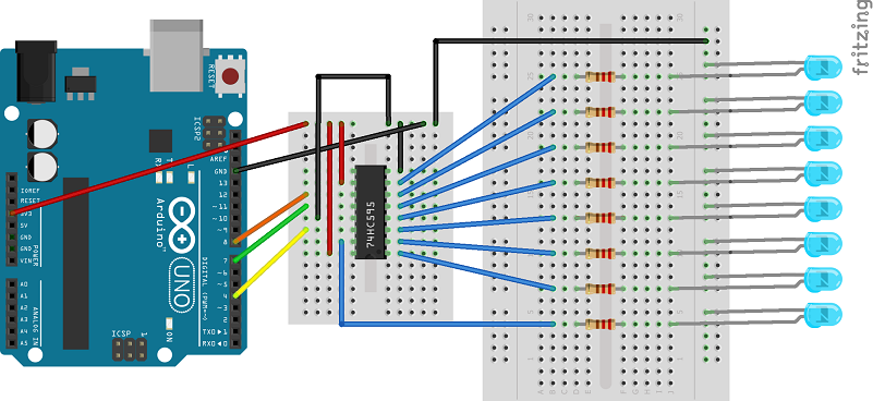
I had this little project in mind but after chewing on it for a while I figured that to achieve my goal I would need more pins than the Arduino Uno can offer. I started looking at what my options were and soon I found something that looked very promising – shift registers (yes, I realize that this is a very basic stuff for people familiar with elementary electronics but sadly I am not one of them). Conceptually, the way shift registers work is simple – you feed a shift register bit by bit (serial-in) and then tell it to output all data at once (parallel-out). (The opposite (i.e. parallel in, serial out) is also possible but this is out of scope of this post.) Translating this to Arduino terms – with one output pin to send the data and a couple of additional output pins to control the shift register we can have tens of output pins. In the simplest case “tens” means actually 8 but shift registers can be cascaded and each additional register adds 8 additional output pins. To try this out I got myself a few 74HC595 shift registers and a bunch of LEDs and resitors and build this circuit:
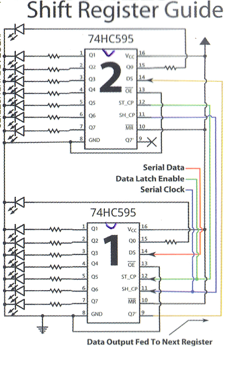
One thing that turned out to be very helpful was a small sheet I got when I bought the shift registers showing how to cascade them. Even though I was not cascading shift registers (I was too cheap and bought just 10 LEDs) it helped me connect all the power and ground wires to the correct pins. I actually decided to scan the sheet and attach it to this post because I am sure I will lose it sooner than later and won’t be able to find it when I need it. Here it is:
Then I had to breathe some life into all the wires and ICs so I wrote some code. I was surprised when it turned out that you literally need less than 10 lines of code (and some data) to get the whole thing up and running:
The code is simple. Since I have just 8 LEDs I can use a byte value to control which of the LEDs should be on. If a bit corresponding to an LED is set to 1 I will turn the LED on, otherwise I will turn it off. The values are stored in an array and every 300th millisecond or so I take the next value from the array and use it turn the LEDs on or off. When I reach the end of the array I start from the first element. Even though the code is so simple there are two interesting bits there. The first one is controlling the shift register. The second one (related to the first one) is how the shiftOut function works. As I said above we need three wires to control the register. They are connected to pins labeled as latch, clock and data in the code. We set latch to LOW to tell the shift register that we are going to send data. Once we send all the data we need to set latch to HIGH. To send the data we use the shiftOut function. What this function does is it reads the passed value bit by bit and for each bit it sets the clock pin to LOW then it sets the data pin to LOW or HIGH depending on the value of the bit and then it sets the data pin to HIGH. It is actually pretty easy to write a counterpart of the shiftOut function on your own. Here is what I came up with (I skipped the bitOrder parameter as I did not need it):
You can replace the call to the shiftOut function with a call to the myShiftOut function in the first snippet and it will continue to work the same way.
That’s more or less it. Simple but very powerful (and fun)!
When I heard about Arduino a couple years ago (yes, I was a bit late to the party) I immediately fell in love with it. The main reason was that it allowed me to try things that otherwise would require a lot of time and effort from a total electronics noob like me. With Arduino, a breadboard, a few LEDs and a couple of cables I was ready to write my very first program – controlling the LED with Arduino. It was fun! But I wanted to do something more interesting. I figured that while flashing a LED is fun displaying something on a screen must be even more fun. Soon I found that it was possible to buy a cheap Nokia 5110 LCD displays on ebay. I had some doubts whether I would be able to make it work but figured out that even if I wouldn’t I could always use it as a key chain or a similar geeky gadget. Indeed, when the display arrived I did have some problems to make it work. First, I was not sure how to connect the display to Arduino. Even though I found a few websites that showed how to do that I had hard time to make it work. I also tried a couple of sample programs that in theory should display something on the display but in practice they did not. Eventually, I found that one of the cables were connected incorrectly and the sequence to initialize the display did not work (at least on my display). Seeing something on the screen was a huge step forward and I finally could think about using the display for my own purpose. I decided that I could do a digital clock as it seemed a reasonably sized project which would still require understanding how the display really works. First I wanted to “design” fonts for the clock. For this I just used graph paper and this reminded me designing sprites for my C-64 in the late eighties. After designing all digits I had to understand how to encode these so that they could be drawn easily on the screen. I found the datasheet for the PCD8544 which is a controller for the display. This was the first time in my life I had to read a datasheet for an electronic component but I was able to understand what the most important things and the datasheet turned out to be an interesting read. Soon, I found what I wanted – the display has 6 rows and 84 columns. Each column in a row has 8 pixels. To draw something on a screen first you need to set a pointer (row and column) and then write a byte (8 bits) to draw the column. When you draw a column the pointer automatically advances to the next column – this is handy since you don’t really have to set the pointer all the time if you draw something like a bitmap. The mechanics of drawing on the screen surprised me. Firstly, I found it kind of similar to advanced graphics modes on 8-bit computers. Secondly, it was interesting to see that the programmer’s convenience totally lost with the low level design of the controller (or may be I am just spoiled by higher level APIs which allow me just to pass x and y to draw a point). After figuring out how drawing looks like encoding my digits was relatively simple. Now that I was able to draw digits on the screen it was the time to implement the clock. Initially I wanted to use the loop function but I quickly realized that it would not really work for a clock. I did not know how long drawing would take and therefore the clock would not work correctly. I could calculate how much time drawing took and then cut the wait time accordingly but it didn’t feel like the right solution. Obviously, there was one more (and I believe the only correct for this kind of problem) solution – interrupts. The only problem was to set everything up correctly. I spent some time reading Arduino datasheet but things did not really want to work. Fortunately I found this page which helped tremendously. After setting up interrupts things went smoothly and soon I had my digital clock up and running. I actually ended up using both the loop function and the interrupt. The interrupt just increases the timer while all the drawing takes place in the loop function. This way I don’t have to worry that drawing takes too much time and when a new interrupt happens the previous one is still being handled. That’s pretty much it. Here is a short video showing the clock in action:
If you want to try my project here is how I connected the Nokia 5110 display to Arduino:
One more thing I always wanted to do but never really have had time to do was to add some buttons to enable setting the clock – at the moment the clock always starts at 00:00. Maybe one day I will come back to this project again (like I did today just to publish it) and will add the buttons…