Necessity is mother of invention. Even though in this case there was not a lot of invention, there was necessity. I wanted to play with the ESP8266 module and I wanted it badly. Unfortunately, I could not find any FTDI in my drawers, so I had to find a different way of talking to my ESP8266. I quickly concluded that I could use either Arduino or Raspberry Pi. I decided to start with Arduino but for whatever reason could not make it work. A little desperate, I decided to try Raspberry PI. This, thanks to the information I found on the Internet, got me much further. I found a few articles scattered over the web and after combining various pieces of information I was able not only to talk to my ESP8266 but also reprogram it. I decided to write this post so that all the information I found is in one place. Let’s get started.
The idea is to connect an ESP8266 module to Raspberry Pi’s GPIO serial pins and then use a serial communication terminal like minicom or screen to talk to the module. Before we can do this, we need to reconfigure our Raspberry Pi so that the OS is not using the serial interface. The first step is to disable serial logins. The easiest way to achieve this is to use raspi-config. Start the the raspi-config with sudo raspi-config, go to Interfacing Options and then to Serial. You will be asked two questions – answer them as follows:
- Would you like a login shell to be accessible over serial?
Select: No - Would you like the serial port hardware to be enabled?
Select: Yes
The second thing to do is to switch off sending bootup info to serial by removing references to ttyAMA0 in the /boot/cmdline.txt file – e.g.
dwc_otg.lpm_enable=0 console=ttyAMA0,115200 kgdboc=ttyAMA0,115200 console=tty1 root=PARTUUID=9815a293-02 rootfstype=ext4 elevator=deadline fsck.repair=yes rootwait
becomes:
dwc_otg.lpm_enable=0 console=tty1 root=PARTUUID=9815a293-02 rootfstype=ext4 elevator=deadline fsck.repair=yes rootwait
Finally, you need to restart your Raspberry Pi for changes to take effect
sudo reboot now
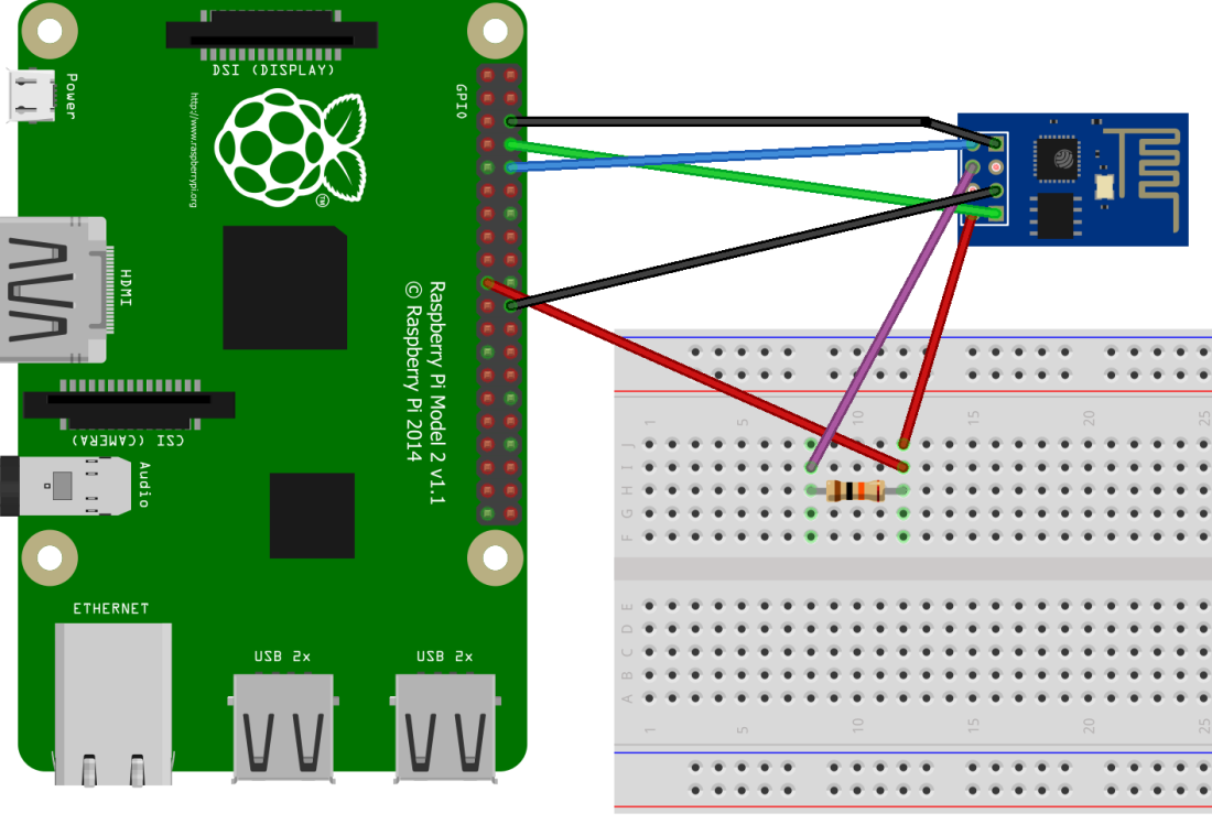
Now, that we prepared our Raspberry Pi we need to wire the ESP8266 module. You need to power down Raspberry PI and connect your ESP8266 module as per the diagram below.

ESP8266   Raspberry Pi

GND       GND

3.3V      3.3V

RXD       UART_TXD

TXD       UART_RXD

CH_PD     3.3V (via a pull down resistor)
After wiring the ESP8266 module to the Raspberry Pi has been completed we can boot the Pi and connect to the ESP8266 using screen (I am using screen because it is installed by default but you can use minicom if you prefer):
screen /dev/ttyAMA0 115200
To see if we connected successfully let’s send some commands to the module (note: when using screen you need to press Enter and CTRL+J to send the command).
Check if AT system works (AT):
AT

OK
Display the version (AT+GMR)
AT+GMR

AT version:1.2.0.0(Jul  1 2016 20:04:45)

SDK version:1.5.4.1(39cb9a32)

Ai-Thinker Technology Co. Ltd.

Dec  2 2016 14:21:16

OK
Connect to WiFi (a series of commands)
AT+CWMODE_CUR=1

OK
AT+CWJAP_CUR="ssid","pwd"
WIFI CONNECTED
WIFI GOT IP
OK
AT+CWJAP_CUR?
+CWJAP_CUR:"ssid","18:a6:f7:23:9e:50",6,-52
OK
AT+CIFSR
+CIFSR:STAIP,"192.168.0.110"
+CIFSR:STAMAC,"5c:cf:7f:36:cd:31"
The full list of AT commands can be found on the espressif’s web site in the documents section – look for ESP8266 AT Instruction Set. Note that some commands from the document may not work if you are using an older version of the firmware.
We are able to communicate with our ESP8266. Now, let’s try updating the firmware. First, we need to power down the PI again and connect the GPIO0 pin of the ESP8266 to the PI’s ground pin. This will make the module run in the flash mode.
The next step is to install the esptool which we will use to transfer firmware files to the module:
sudo apt-get update

sudo apt-get install python

sudo apt-get install python-pip

sudo pip install esptool
Finally, we need a firmware that we will flash to the device. We can get a new firmware by cloning the espressif’s ESP8266_NONOS_SDK repo:
git clone https://github.com/espressif/ESP8266_NONOS_SDK
After the repo has been cloned we need to go to the bin folder and run the following command:
esptool.py --port /dev/ttyAMA0 --baud 115200 write_flash --flash_freq 40m --flash_mode qio 0x0000 boot_v1.7.bin 0x1000 at/512+512/user1.1024.new.2.bin 0x7E000 blank.bin
The output of the command should look like this:
esptool.py v2.0.1

Connecting...

Detecting chip type... ESP8266

Chip is ESP8266

Uploading stub...

Running stub...

Stub running...

Configuring flash size...

Auto-detected Flash size: 1MB

Flash params set to 0x0020

Compressed 4080 bytes to 2936...

Wrote 4080 bytes (2936 compressed) at 0x00000000 in 0.3 seconds (effective 121.5 kbit/s)...

Hash of data verified.

Compressed 427060 bytes to 305755...

Wrote 427060 bytes (305755 compressed) at 0x00001000 in 27.9 seconds (effective 122.3 kbit/s)...

Hash of data verified.

Compressed 4096 bytes to 26...

Wrote 4096 bytes (26 compressed) at 0x0007e000 in 0.0 seconds (effective 4538.5 kbit/s)...

Hash of data verified.
Once the process is complete we can power down the Raspberry Pi and disconnect the ESP8266 GPIO0 pin from GND to make it run again in the normal mode. Now, we can start the PI, and dump the ESP8266 firmware version with the AT+GMR command:
AT+GMR

AT version:1.4.0.0(May  5 2017 16:10:59)

SDK version:2.1.0(116b762)

compile time:May  5 2017 16:37:48

OK
This is a much newer version than what we originally had so we were able to flash our ESP8266 successfully. Yay!
Acknowledgements:
The following articles were instrumental in writing this post:

can i use this technique to load any code onto the esp8266? like any code for sensor or any kind ?
LikeLike
You should be able to, yes.
LikeLike
Thank you very much for this throughout guide. Works like a charm!
LikeLiked by 1 person
is it safe to power ESP8266 during flashing via RaspPi and not independently? What are the risks if any? Thanks
LikeLike
I didn’t see any problems. If you are concerned you can provide power from an external source.
LikeLike
Pardon my ignorance, but why were you not able to connect directly to the ESP8266 from the Pi without the breadboard? If you went GND->GND, TXD/RXD. and then Pi3.3 -> ESP3.3, would that not work? I’m looking at flashing some sonoffs here shortly and found your guide. Thank you for putting it together.
LikeLike
As per the diagram there is a pull down resistor there so having the breadboard was convenient.
LikeLike
when i wire it as in the first diagram, and run `screen` command, i get no visual feedback when trying to type AT commands (and no responses). i also don’t see the blue light lighting up on the eps8266 board. finally trying esptool says can’t connect. any ideas?
LikeLike
Did you follow this: “note: when using screen you need to press Enter and CTRL+J to send the command”?
LikeLiked by 1 person
Is the red wire from the raspi drawn from the right pin? It looks to me as it is from pin 19 MOSI (GPIO10), but should be pin 17 (one up).
LikeLike
I think you are right – it seems that this PIN and the GROUND on the second picture are off by one. Good catch!
LikeLike
The AT and AT+GMR commands work fine via picocom since picocom is configured to map Tx’s Line-Feed to Carriage-Return + Line-Feed:
picocom –baud 115200 –omap crcrlf /dev/ttyS0
AT+GMR
AT version:1.2.0.0(Jul 1 2016 20:04:45)
SDK version:1.5.4.1(39cb9a32)
v1.0.0
Mar 11 2018 18:27:31
OK
The esptool fails to connect, I guess because pyserial does not add Carriage-Return before Line-Feed.
I type:
esptool –port /dev/ttyS0 –baud 115200 chip_id
and I get:
esptool.py v2.5.1
Serial port /dev/serial0
Connecting…….._____….._____….._____….._____….._____….._____….._____
A fatal error occurred: Failed to connect to Espressif device: Timed out waiting for packet header
Just to verify it is a serial communication fault, i changed baud to 57600 and I got a faulty 0x08 head of packet due to a wrong baud rate. I got:
esptool.py v2.5.1
Serial port /dev/serial0
Connecting…….._____….._____….._____….._____….._____….._____….._____
A fatal error occurred: Failed to connect to Espressif device: Invalid head of packet (0x08)
I rule out faulty wiring, unstable power, etc. since the AT commands are functional but esptool is not.
Any idea how to fix it?
LikeLike
Unfortunately I don’t know. Maybe try using `–trace` to get more details about what’s going on?
LikeLike
Thank you for your prompt advise.
I did so and finally I found the fault.
I do appreciate your advice.
LikeLike
I am glad that you were able to figure this out!
LikeLike
Dear moderator,
I’d like to delete my comment since I figured out how to fix it:
The AT commands are functional if GPIO0 not grounded during reset and esptool is functional if GPIO0 grounded during reset.
I other words, I figured out my fault, no need to ask this forum for advise about this issue.
Thank you,
Hezi
LikeLike
Hello, after installing esptool and cloning the repo, when I run the esptool command I get the following error
Serial port /dev/ttyAMA0
Connecting…
Traceback (most recent call last):
File “/usr/local/bin/esptool.py”, line 3201, in
_main()
File “/usr/local/bin/esptool.py”, line 3194, in _main
main()
File “/usr/local/bin/esptool.py”, line 2883, in main
esp = ESPLoader.detect_chip(each_port, initial_baud, args.before, args.trace)
File “/usr/local/bin/esptool.py”, line 274, in detect_chip
detect_port.connect(connect_mode)
File “/usr/local/bin/esptool.py”, line 475, in connect
last_error = self._connect_attempt(mode=mode, esp32r0_delay=False)
File “/usr/local/bin/esptool.py”, line 455, in _connect_attempt
self.sync()
File “/usr/local/bin/esptool.py”, line 394, in sync
timeout=SYNC_TIMEOUT)
File “/usr/local/bin/esptool.py”, line 337, in command
self.write(pkt)
File “/usr/local/bin/esptool.py”, line 300, in write
self._port.write(buf)
File “/usr/lib/python2.7/dist-packages/serial/serialposix.py”, line 538, in write
raise writeTimeoutError
serial.serialutil.SerialTimeoutException: Write timeout
Can someone please tell me why I’m getting this error? Could be that the module is not connected to the Wifi? I ran the AT commands, and it did connect to the Wifi.
LikeLike
Apologies for my ignorance, but I’ve always been curious if the pull-down resistor is absolutely needed or if you can get away with not using one. I have an esp8266 coming in today but don’t have a spare resistor handy and no broken appliances I can harvest one from.
LikeLike
I have not tried without the pull-down resistor but I think it may not work or may not work reliably if you remove it.
LikeLike
Hi, do you know where I could find the factory image? I used the workthrough above and it seems to have bricked my ESP.
LikeLike
I would recommend checking https://github.com/espressif. Another way to go about it is to dump a firmware from another ESP. I think you should be able to do this in a similar way I did it in https://blog.3d-logic.com/2022/04/27/cloud-enabled-commodore-64-part-v-do-it-yourself/ (see the “Backup the C64 WiFi Modem firmware (optional)” section)
LikeLike
I did the same and flashed one of the FWs here and it helped. http://domoticx.com/esp8266-wifi-at-firmware/
LikeLike